Once the house started taking shape I thought that it might be a good idea to add a remote controlled car to the project. I found just the right one, the Orlando Hunter at a 1:35 scale.
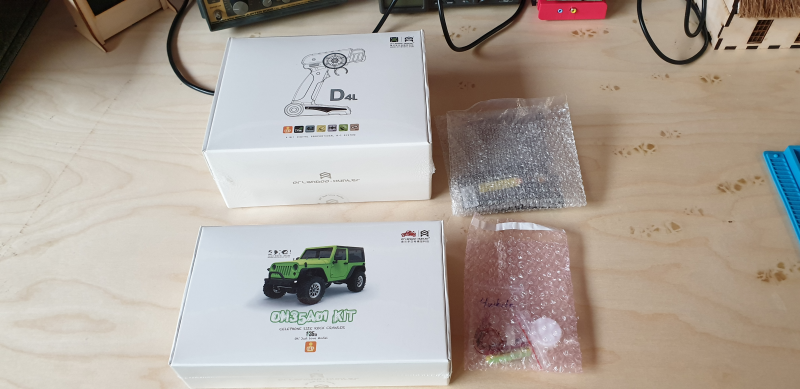 Figure 1: The Orlando Hunter
I have to admit that I didn’t quite realise what I was letting myself into. This was the first time I built a remote controlled car and it probably wasn’t the best idea to start with such a detailed and small scale version. But, that is what the exhibit needed and that is what it was going to get.
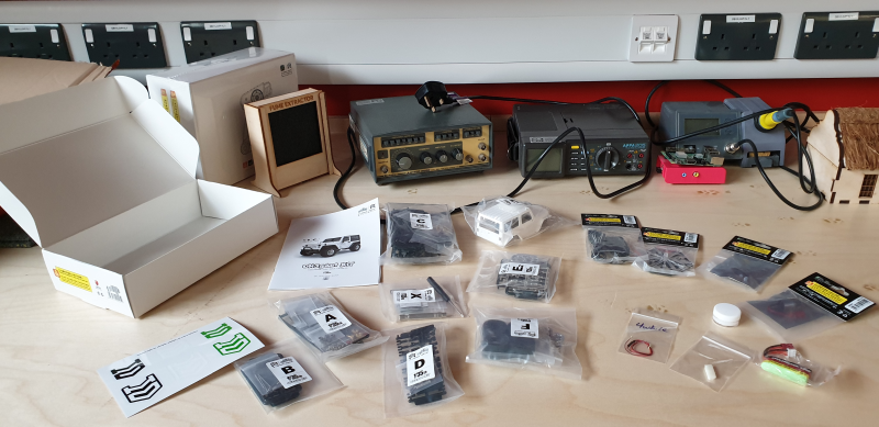 Figure 2: Lots of bits
Thanks to the Chinglish instructions it took me about two hours to assemble the diff and axle. From the photo (Figure 5) you’ll notice that I couldn’t get the bearings to fit properly in the axle. Eventually I managed to figure out what the instructions were trying to tell me and I could correct the assembly. Also, I dicsovered, circlips would rather dig into my soft fingers than clip around a metal rod.
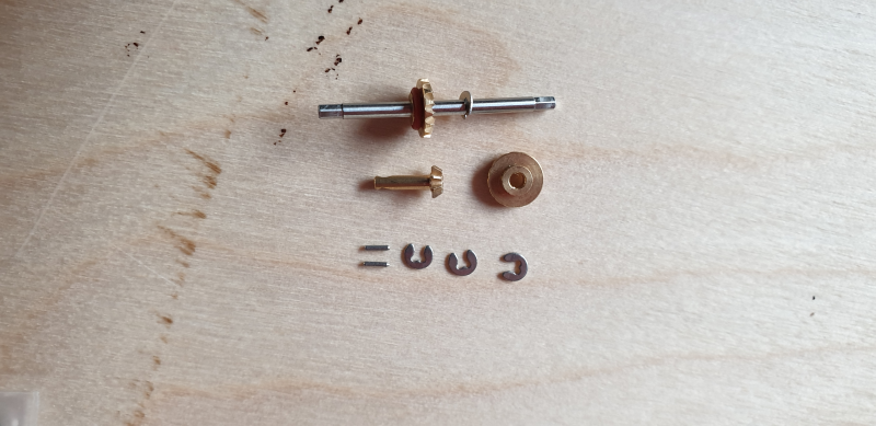 Figure 3: Tingy little circlips which would much rather dig into my finger than clips around the rod.
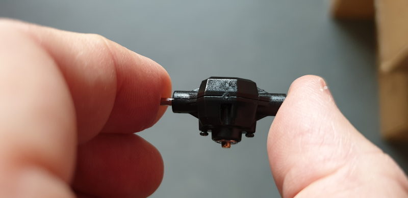 Figure 4: The diff is done.
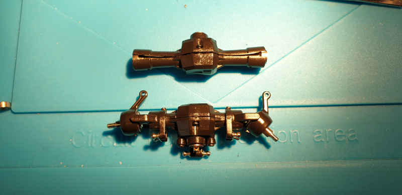 Figure 5: The axles. The top axle still had a problem here but eventually I managed to decipher the instructions and assemble it correctly.
The main lights on the car are normal 5mm LEDs but for the hazards, reverse and break lights, surface mount LEDs are used. If you are not familiar with surface mount components … the photo (Figure 6) below shows two of the LEDs next to an AA battery.
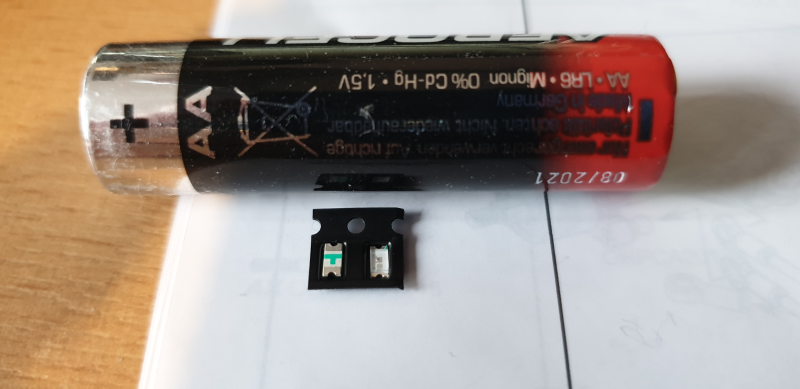 Figure 6: Show the size of surface mount LEDs again an AA battery
Miniscule components would not have been a problem if it wasn’t for the thermostat of my soldering iron that was busy dying. Not one to blame my tools I struggled for hours to do the soldering on the car and only right at the end I realised it wasn’t me that was being clumsy but a faulty thermostat. I was quite relieved when I discovered the problem as I was getting terribly frustrated with myself. I always thought my soldering was pretty good but this project was about to prove me wrong (except that, in the end, it didn’t).
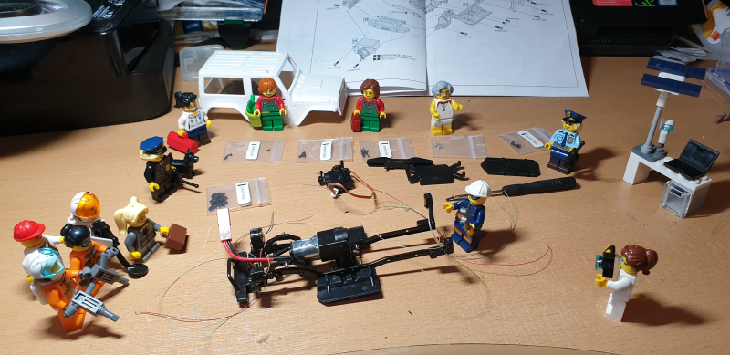 Figure 7: Our team of engineers inspecting progress of the assembly
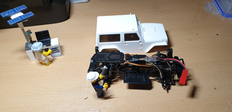 Figure 8: Progress
I had one unfortunate event. Figure 9 shows the axle assembly. In the middle at the bottom is, what I believe is called, the U-joint. A part of this is a tiny cube with four pins sticking out of it. I found a picture of the parts on the Internet (Figure 10). There are 5 of these little cube parts at the bottom left. If I remember correctly I had only two or three, just enough with no extras. Well, I managed to break one of the little pins.
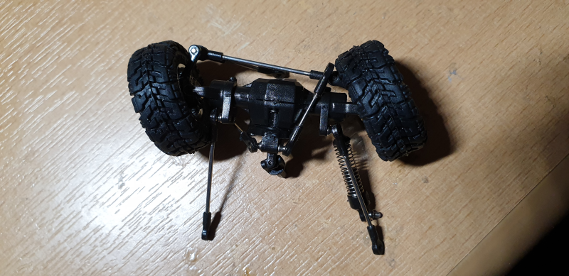 Figure 9: The axle assembly
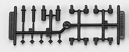 Figure 10: The U-joint parts.
However, I managed to turn one of my most depressing moments into one of being totally chuffed with myself. I took a paper clip and cut a little rod out of it and then I drilled a hole through the cube into which the rod would fit tightly – and voilah – the day was saved. If you look closely at the U-joint in figure 9 you can see the tiny bit of silver in the hole. That is the paper clip rod which is replacing the plastic pin.
Some many hours later the biggest part of the build was done. The next step would be to paint the body. I tested everything at this point and all was working.
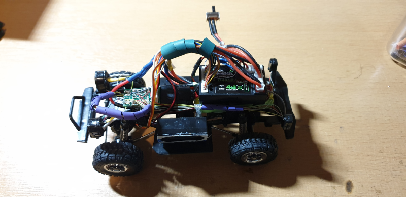 Figure 11: All the insides are assembled and working.
Some years back I bought an airbrush set from Lidl but I have never used it. Now was my chance. I set off to the Warhammer shop in Newcastle and bought bright green and purple paint (the WES colours). This was also my first effort with the airbrush.
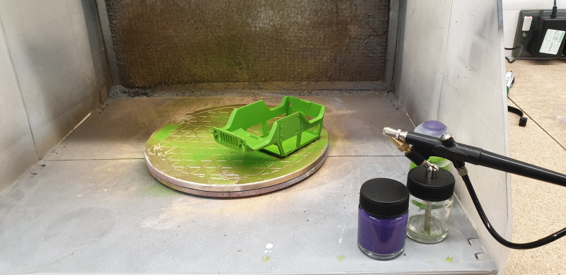 Figure 12: The paint job.
So it is almost all done and dusted. My idea is to allow visitors to the exihibit to try and drive the car into the garage and I’m not sure that the little bits such as the side view mirrors will just break off, so I still have to decide whether I’ll be glueing them on. I also want to change the switch and charging connector to contact points that I can stick somewhere on the body or the crashbar in the front so that the car be driven into a position in the garage where the battery gets charged automatically.
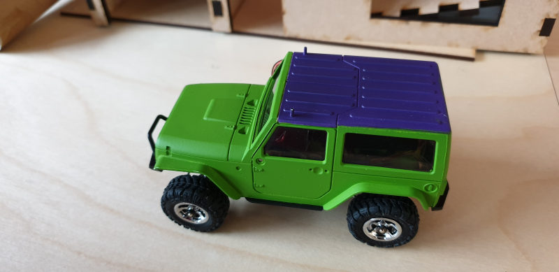 Figure 13: We have a car!